Managing Modbus TCP definitions
Modbus TCP is a communication protocol typically used by facility or building level assets. Hyperview allows the creation of Modbus TCP definitions to handle the monitoring of such equipment separate from auto-discoveries.
A Modbus TCP definition can be assigned to any number of assets to enable monitoring on that asset if they share the same object mapping, but only one definition can be applied to an individual asset at a time.
Adding a Modbus TCP definition
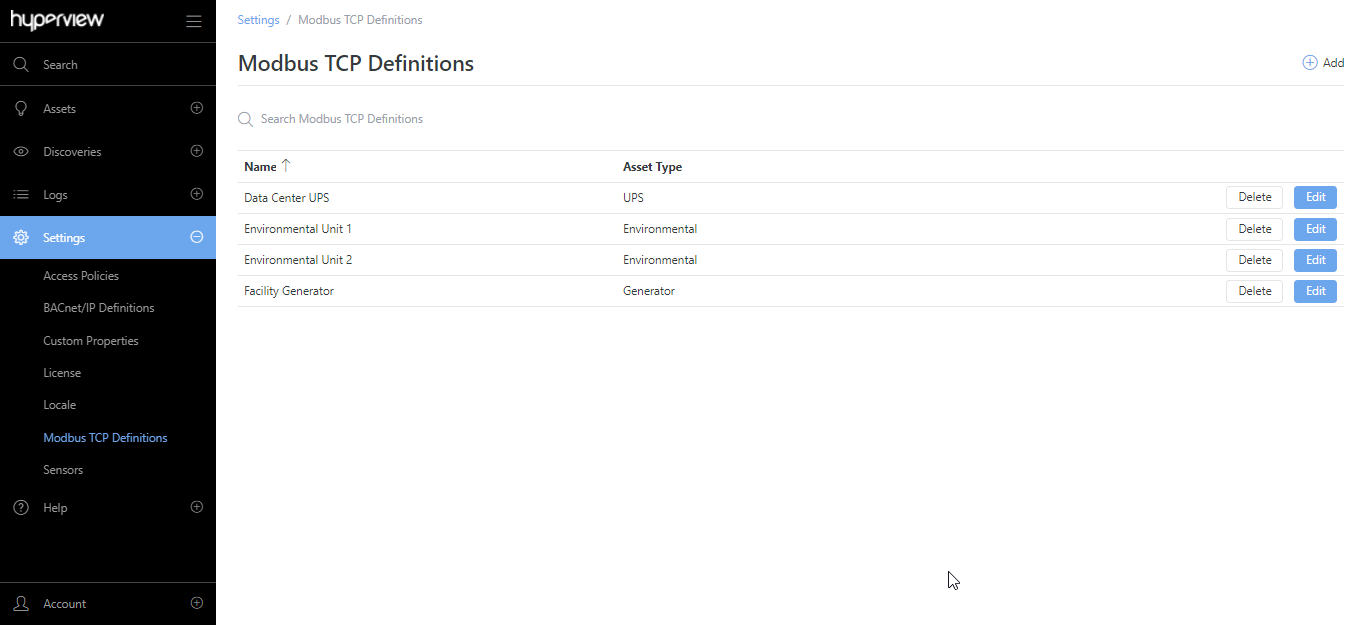
Go to Settings → Modbus TCP Definitions.
Click Add. Alternatively, if you have no Modbus TCP definitions, click Add new Modbus TCP definition.
Enter a Name and Asset Type for the definition, and click Save.
A success message will appear, and the Overview page of the new Modbus TCP definition will be displayed. Proceed to add sensor definitions.
Tip
Refer to the “Adding a single asset” section in Adding assets for steps to manually add assets with a Modbus TCP monitoring profile.
Adding a numeric sensor definition
While editing or adding the Modbus TCP definition, click the Numeric Sensors tab.
Click Add. Alternatively, if there are no existing sensor definitions, click Add Numeric Sensor.
Provide values for Address, Type, Data Type, Sensor Type, Sensor Name, Sensor Unit, and Multiplier. Note that the Sensor Name and Sensor Unit fields will only appear once you have selected a Sensor Type.
Click Save.
A success message will appear, and the numeric sensor definition will be listed in the grid. Repeat the steps to add additional sensor definitions as appropriate.
Adding a non-numeric sensor definition
While editing or adding the Modbus TCP definition, click the Non-numeric Sensors tab.
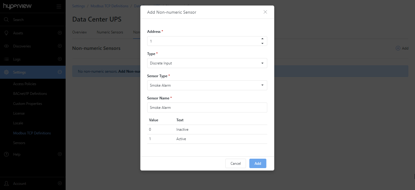
Click Add. Alternatively, if there are no existing sensor definitions, click Add Non-numeric Sensor.
Provide values for Object Instance, Type, Sensor Type, Sensor Name. Additionally, you can modify Value mappings (for all types) or add Value mappings (for non-binary types).
Click Save.
A success message will appear, and the non-numeric sensor definition will be listed in the grid. Repeat the steps to add additional sensor definitions as appropriate.
Updating a Modbus TCP definition
Go to Settings → Modbus TCP Definitions → Edit.
Update values from the Overview or Numeric Sensors tab as required, and save your changes.
A success message will appear for each change, and the current page will reload to reflect the change.
Updating or deleting a sensor definition
While on the Numeric Sensors tab or the Non-numeric Sensors tab for a Modbus TCP definition:
Click Edit to update values for an existing sensor definition. Click Save to save the updated sensor definition.
Click Delete → Delete to delete an existing sensor definition.
A success message will appear in each case, and the current page will reload to reflect the change.
Deleting a Modbus TCP definition
You cannot delete a Modbus TCP definition that has associated assets. After you have updated associated assets (from each asset’s Information → Monitoring page):
Go to Settings → Modbus TCP Definitions.
Click Delete → Delete for the intended definition.
A success message will appear, and the current page will reload to reflect the change.