AssetTracker hardware
Supported hardware
The AssetTracker RFID solution is currently certified with Digitalor asset-tracking hardware.
Tip
Hyperview’s automated asset-tracking system can be tested and certified with additional asset-tracking hardware solutions. We encourage vendors to contact Hyperview if they are interested in having their asset-tracking hardware system certified.
The supported hardware models are:
The V5008 AIoT Smart Gateway (MQTT) running firmware version 3.x
The V6800 AIoT Gateway (MQTT) running firmware version 1.x
Please contact the Hyperview Sales or Support teams for more information.
Installation
Selecting a Hardware Configuration
AssetTracker can be installed in three different configurations:
One-to-One: One Expansion Hub to one Gateway (V5008 AIoT)
Daisy Chain: Up to 5 Expansion Hubs to one Gateway (V5008 AIoT)
One-to-Many: Up to 24 Expansion Hubs to one Gateway (V6800 AIoT)
Example Daisy Chain Deployment
For installing AssetTracker in multiple racks in a row, you may daisy-chain up to five Expansion Hubs to a single Gateway. The maximum length of the cables from the Gateway to the last Expansion Hub in the chain must not exceed 20 meters (65 feet).
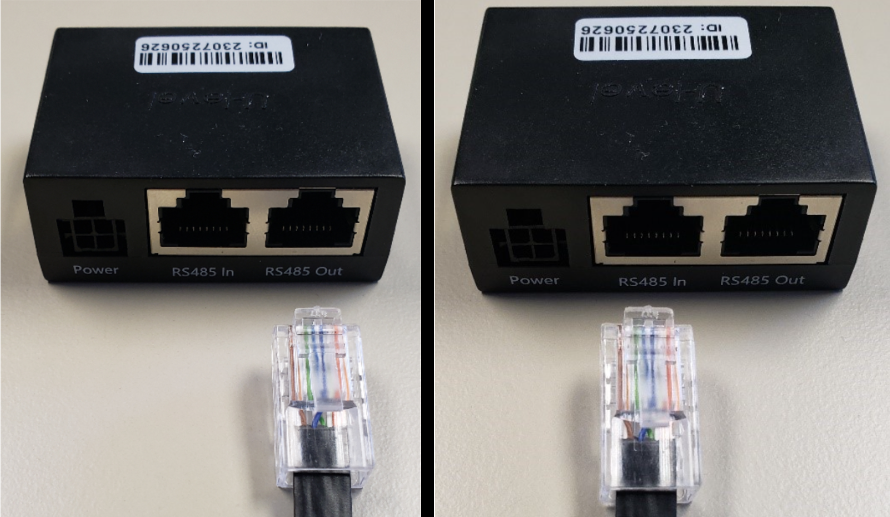
Each Master Module has an address between 1 (one) and 5 (five). Each Master Module must have a unique address in the Daisy Chain configuration. The address specification is printed on the Master Module tag.
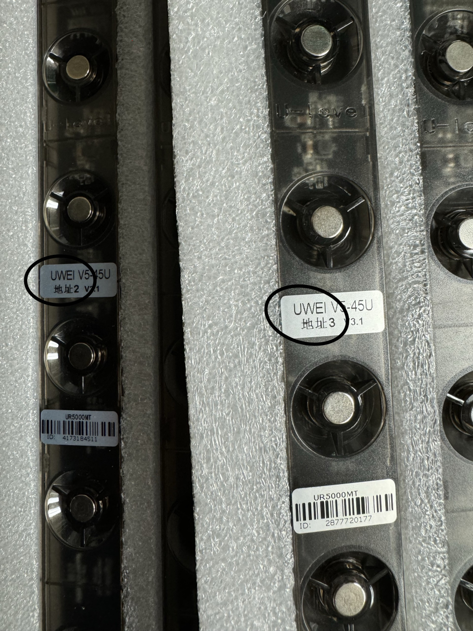
Master Modules with ID and address (Circled)
Network requirements
Important
You must contact our support team to get access to the latest vendor configuration software and documentation.
The Gateway uses port 5656/TCP for management and configuration. The configuration must be done using the supplied tool. It is strongly recommended that the tool be on the same network segment as the Gateway to minimize network-related issues.
Note
To configure a network adapter so that it is on the same subnet as the AssetTracker hardware, it is recommended to follow these steps:
Run (Win+R) ncpa.cpl to open the Network Connections applet
Right-Click and select Properties for the Ethernet adapter
Open the Properties for Internet Protocol Version 4 (TCP/IPv4)
Select “Use the following IP address:”
IP Address: 192.168.100.### (where ### is an available IP address)
Subnet Mask: 255.255.0.0
Default Gateway: IP Address of the network switch or router
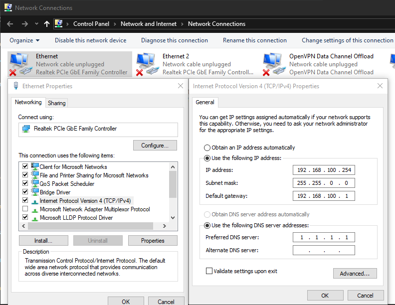
Example Windows Network Connections Configuration
The Gateway communicates with the data collector over port 1883/TCP. Communication is from the Gateway to the Data Collector. The Data Collector setup documentation has more information on the network requirements.
AssetTracker Strip sizing
AssetTracker modules come in 5U and 6U lengths and can be configured to fit any rack RU size.
Installation locations
Typical installation locations include, but are not limited to:
Rack side panel
Rack door
Rack front panel
In all these cases, please:
Verify there is enough space for the modules and 3M adhesive.
Verify there is enough space to mount and remove equipment from the rack.
Verify the door can be opened and closed without interference.
Verify that there is no interference with power, network, and other infrastructure.
Verify that the AssetTracker Strip is supported on a flat surface with no mechanical stress or pressure on it.
Use the adhesive where possible, and if needed, use plastic zip ties for reinforcement. Take care not to add pressure, puncture the casing, or create mechanical stress on the assembled device.
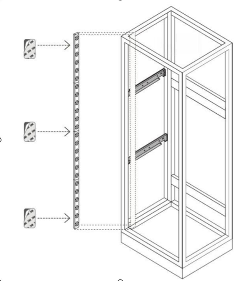
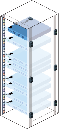
Rack installation example
Assembling Modules
Identify the Master Module. The Master Module has a SATA port above the top-most magnet position. The Extension Modules have male connectors at the top end.
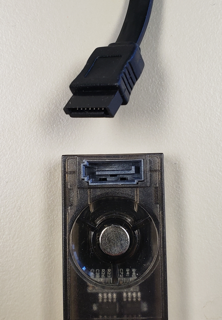
Master Module and SATA Cable
Lay the modules on a flat surface, then snap the male connector on the Extension Module into the female connector on the Master Module. Continue connecting Extension Modules, ensuring that the Master Module is the top-most module in the chain.
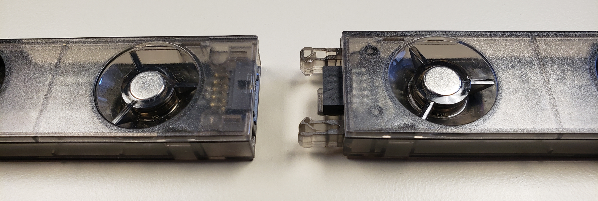
Master Module and Extension Module ends
Installing Modules
Once the AssetTracker Strip is assembled and installed in the selected position, it needs to be connected to an Expansion Hub. Connect the RJ45-to-SATA cable from the Master Module (SATA Port) to the Expansion Hub (V5 Port). Secure the Expansion Hub to the side using the provided 3M adhesive tape or another appropriate means.
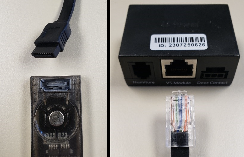
Master Module to Expansion Hub example 1
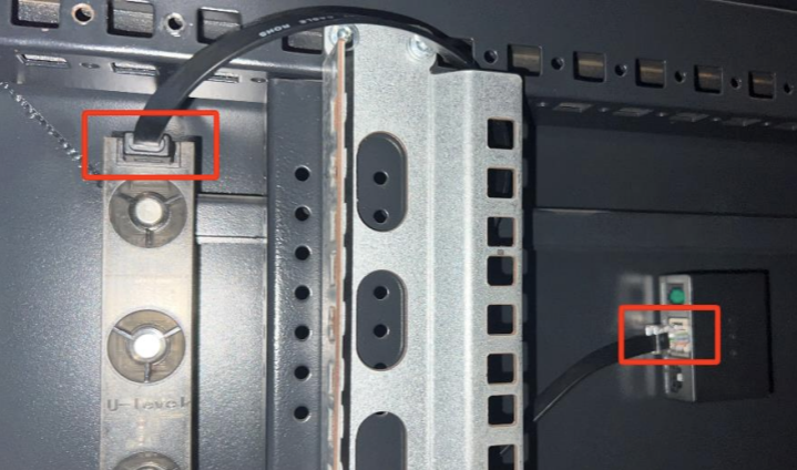
Master Module to Expansion Hub example 2
Connect the RS485 In interface of the Expansion Hub to the U Level port of the Gateway.
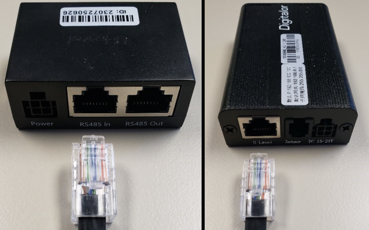
Expansion Hub to Gateway example 1
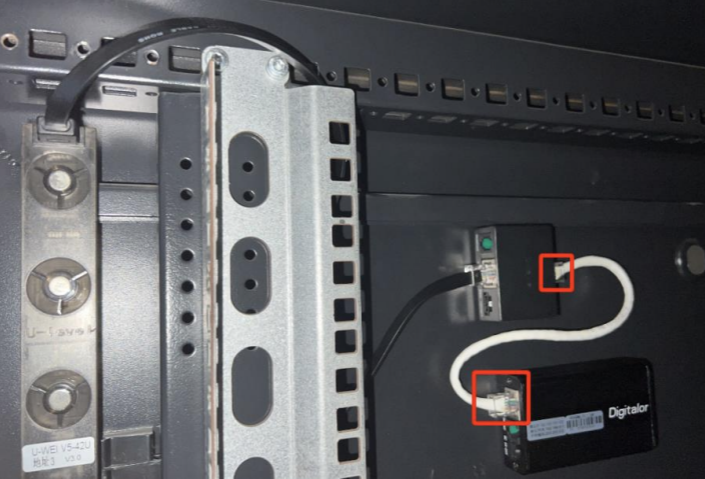
Expansion Hub to Gateway example 2
If the Gateway is a V5008 AIoT, up to 5 Hubs can be daisy-chained together. Connect the RS485 Out Port from the Hub connected to the Gateway to the RS485 In Port of an additional Hub. Note the following:
The maximum cable length from the Gateway to the last Hub in the chain must not exceed 20 meters (65 feet).
Master Module addresses must be unique.
Expansion Hub to Expansion Hub
If applicable, connect the Gateway to a POE power source.
Sensors
Temperature and Humidity Sensors
A Temperature and Humidity sensor package can be connected to the Expansion Hub. Sensors must be connected to the Temperature and Humidity RJ11 port on the Expansion Hub. Up to six sensors can be daisy-chained. Each sensor must have a unique address, typically 10 to 15. The address will be printed on the sensor.
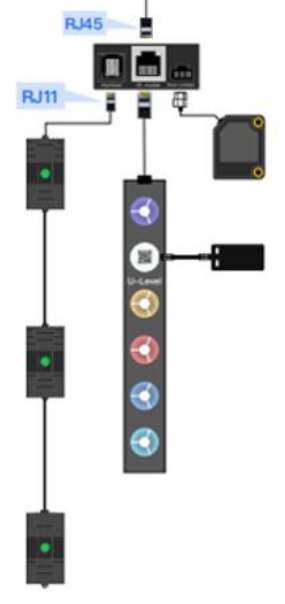
Expansion Hub to sensors
With a six-sensor deployment, three temperature zones (front and back) can be monitored in a rack. Hyperview will automatically calculate the temperature averages and Delta-T values for the zones.
A Rack With Six Temperature and Humidity Sensors
Rack Door Sensors
Rack door sensors can be attached to Expansion Hubs. The C60 Expansion Hub can have a single door sensor. The C68 Expansion Hub can support a dual-door sensor. Please note that the gateway must have the appropriate firmware to support the sensors.
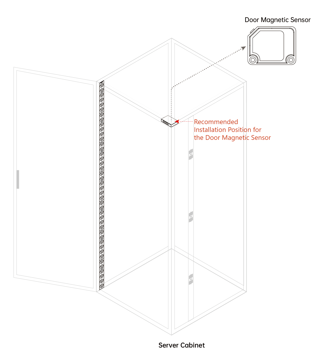
A Rack With A Door Sensor
The ideal distance between the sensor and the rack door when the door is fully closed is roughly 1 cm to 10 cm. This range gives the infrared sensor the most reliable detection range and minimizes false positives caused by surface reflection.
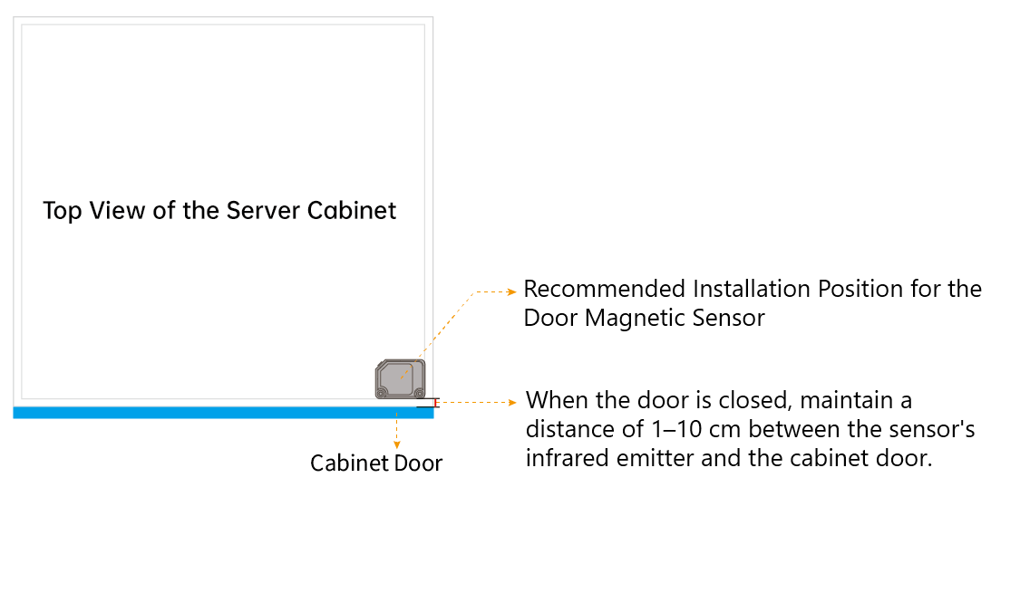
A Rack With A Door Sensor Top View
Important
Once a door sensor is installed on a rack, the “Door Status Sensor” Property must be set. Configure this property by navigating to the Information -> Properties page of the rack.
Installing Asset Tags
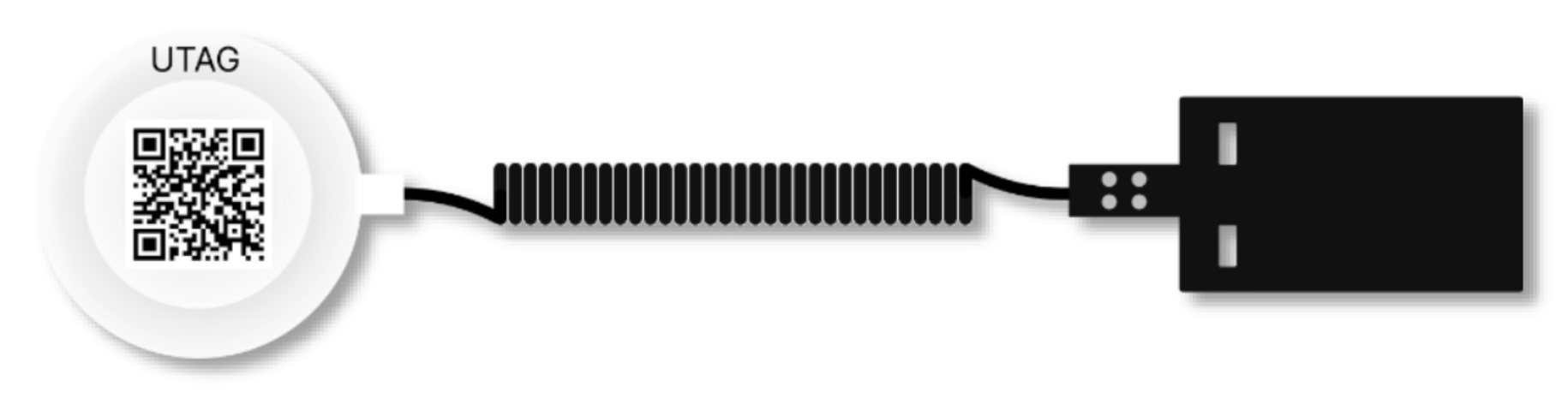
Clean the surface of the asset from dust.
Remove the adhesive cover from the Asset Tag.
Attach the Asset Tag to the asset. Ensure the tag is firmly attached to the asset in a secure location. Avoid air inlets and outlets, asset serial numbers, identification tags, chassis LCD screens, etc.
Connect the magnet of the Asset Tag to the AssetTracker Strip. Ensure it is associated with the asset’s top-most RU module position. For example, if you are tagging a 4U device placed between RU 20 and 23, then associate the tag with the RU23 position.
Asset Tag to AssetTracker Strip
V5008 AIoT network diagram
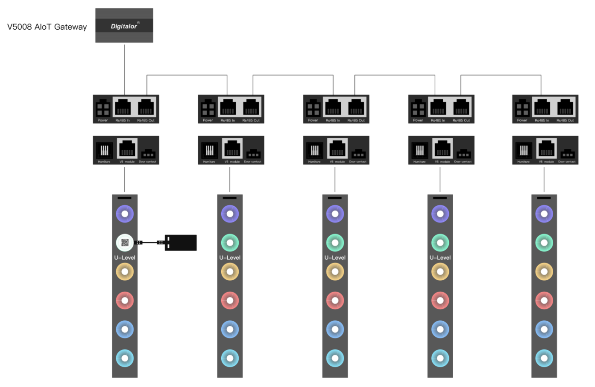
V5008 AIoT network diagram
V6800 AIoT network diagram
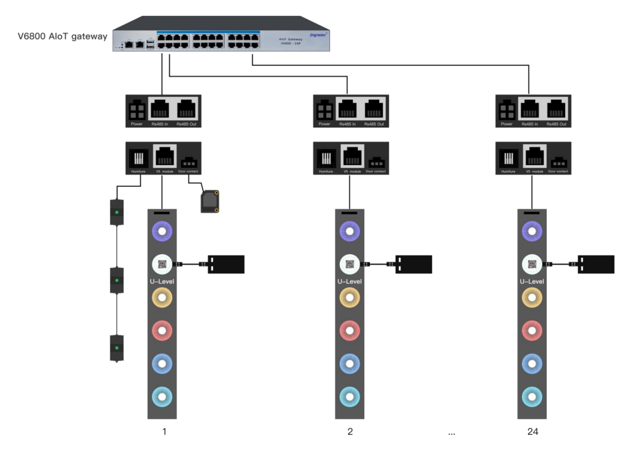
V6800 AIoT network diagram
Modbus address mapping
Master Modules or C68 Expansion Modules (depending on configuration): 1–5
Temperature and Humidity Sensors: 10–15
Noise Sensors: 16–18
Door Sensors: User fixed system assigned addresses
Configuring Modules
Please reference the Configuration Tool User Manual to configure the gateways to communicate with a Hyperview Data Collector. The documentation is available through the Hyperview help desk upon request.