Circuit Network Path
The Network Path tab provides a visual representation of a circuit. It shows the assets and locations that the circuit passes through, and the connections between them, from one end of the circuit to the other. Users can select any asset or connection in the network path to view more information about it, and export the network path as an image or PDF.
Note
The network path is built from the connections that have been added to the circuit. See Creating a New Circuit for more information on adding connections to a circuit.
Navigate to the Connectivity > Circuits page, and click the Circuit ID (or the Details button) of a circuit.
Click the “Network Path” tab. Each asset or location in the circuit is shown as a card with its name, type, status, and location. Each connection is shown, by name, between the two assets that it connects. The port used by each connection is shown on the edge of the asset’s card. For patch panels, the side of the port (Front or Rear) is also shown.
In the example below, the circuit runs from a port on a network switch to a rear port on a patch panel, and then from the corresponding front port on the patch panel to a network port on a server.
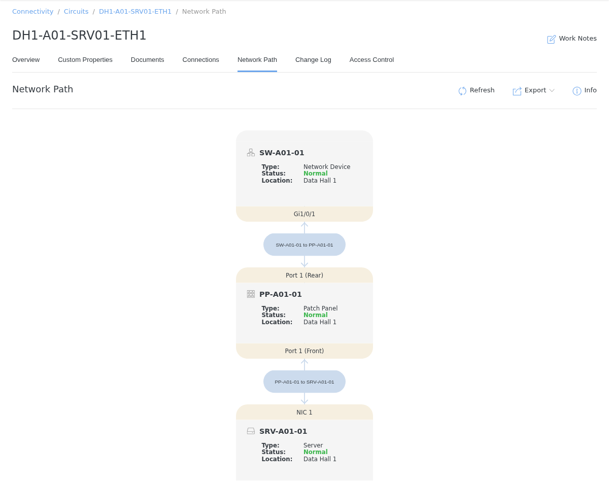
Click and drag to pan the network path. Use the mouse wheel to zoom in and out.
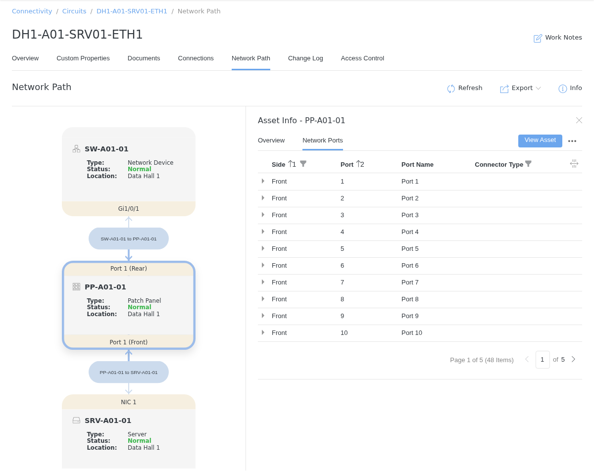
Click an asset in the network path, then click the “Info” button to open the Asset Info panel. The Overview tab shows the asset’s type, status, location, manufacturer, and model, and the Network Ports tab lists the asset’s network ports. Click View Asset to open the asset.
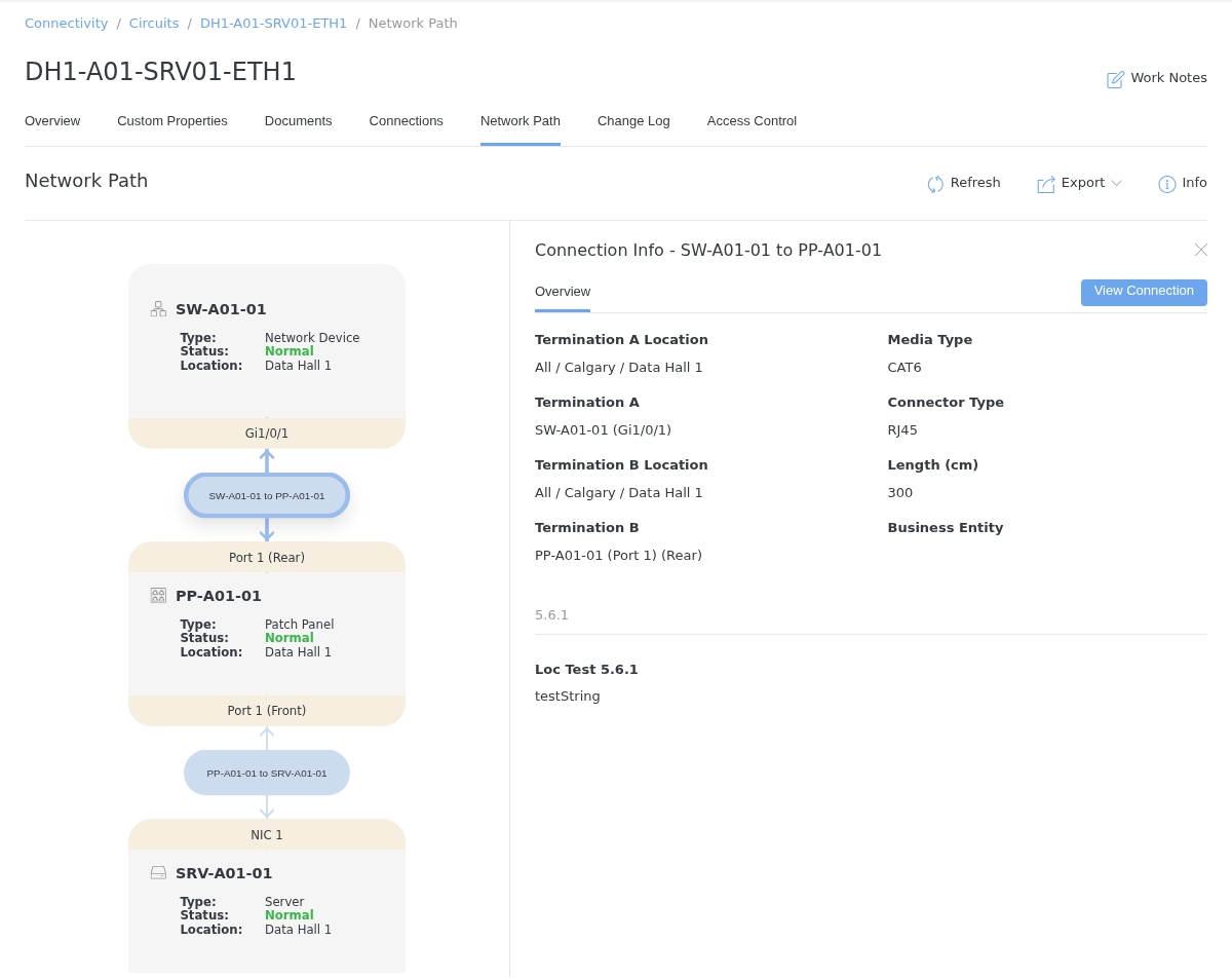
Click a connection in the network path to view the Connection Info panel. The panel shows the connection’s terminations (including the port and, for patch panels, the side), media type, connector type, length, business entity, and custom properties. Click View Connection to open the connection.
Note
While the information panel is open, you can click other assets and connections in the network path to update the panel. Click the “Info” button again, or the close button, to close the panel.
Click “Export” and select JPG, PDF, or PNG to export the network path.
Click “Refresh” to reload the network path after changes have been made to the circuit’s connections.